Daftar Isi (Table Of Content)
Abstrak (Abstract)
Modul ini membahas tentang decoder dan encoder
Tujuan Pembelajaran/Kompetensi Akhir
Mahasiswa diharapkan dapat memahami bagaimana operasi decoder dan encoder
6.1 Pendahuluan
Dekoder merupakan suatu bentuk rangkaian logika yang berfungsi untuk menyederhanakan input yang masuk (berupa biner) supaya lebih mudah dipahami outputnya (dalam bentuk desimal).
A decoder is a multiple-input, multiple-output logic circuit that converts coded inputs into coded outputs, where the input and output codes are different; e.g. n-to- 2n, BCD decoders.
Enable inputs must be on for the decoder to function, otherwise its outputs assume a single “disabled” output code word.
Decoding is necessary in applications such as data multiplexing, 7 segment display and memory address decoding. Figure below shows the pseudo block of a decoder

6.2 Basic Binary Decoder
AND gate can be used as the basic decoding element, because its output is HIGH only when all its inputs are HIGH. For example, if the input binary number is 0110, then, to make all the inputs to the AND gate HIGH, the two outer bits must be inverted using two inverters as shown in figure below

6.2.1 Binary n-to-2n Decoders
A binary decoder has n inputs and 2n outputs. Only one output is active at any one time, corresponding to the input value. Figure below shows a representation of Binary n-to- 2n decoder

2-to-4 Binary Decoder
A 2 to 4 decoder consists of two inputs and four outputs, truth table and symbols of which is shown below.
Truth Table

Symbol

To minimize the above truth table we may use kmap, but doing that you will realize that it is a waste of time. One can directly write down the function for each of the outputs. Thus we can draw the circuit as shown in figure below.
Note: Each output is a 2-variable minterm (X’Y’, X’Y, XY’, XY)
Circuit

3-to-8 binary decoder
A 3 to 8 decoder consists of three inputs and eight outputs, truth table and symbols of which is shown below.
Truth Table

Symbol

From the truth table we can draw the circuit diagram as shown in figure below.
Circuit

Implementing Functions Using Decoders
- Any n-variable logic function, in canonical sum-of-minterms form can be implemented using a single n-to- 2n decoder to generate the minterms, and an OR gate to form the sum.
o The output lines of the decoder corresponding to the minterms of the function are used as inputs to the or gate. - Any combinational circuit with n inputs and m outputs can be implemented with an n-to-2n decoder with m OR gates.
- Suitable when a circuit has many outputs, and each output function is expressed with few minterms.
6.3 Full adder
Equation

Truth Table

From the truth table we know the values for which the sum (s) is active and also the carry (c) is active. Thus we have the equation as shown above and a circuit can be drawn as shown below from the equation derived.
Circuit

An encoder is a combinational circuit that performs the inverse operation of a decoder. If a device output code has fewer bits than the input code has, the device is usually called an encoder. e.g. 2n-to-n, priority encoders.
The simplest encoder is a 2n-to-n binary encoder, where it has only one of 2n inputs = 1 and the output is the n-bit binary number corresponding to the active input.

6.4 Octal-to-Binary Encoder
Octal-to-Binary take 8 inputs and provides 3 outputs, thus doing the opposite of what the 3-to-8 decoder does. At any one time, only one input line has a value of 1. The figure below shows the truth table of an Octal-to-binary encoder.
Truth Table

For an 8-to-3 binary encoder with inputs I0-I7 the logic expressions of the outputs Y0-Y2 are:
Y0 = I1 + I3 + I5 + I7
Y1= I2 + I3 + I6 + I7
Y2 = I4 + I5 + I6 +I7
Based on the above equations, we can draw the circuit as shown below
Circuit

6.6 Decimal-to-Binary Encoder
Decimal-to-Binary take 10 inputs and provides 4 outputs, thus doing the opposite of what the 4-to-10 decoder does. At any one time, only one input line has a value of 1. The figure below shows the truth table of a Decimal-to-binary encoder.
Truth Table

From the above truth table , we can derive the functions Y3, Y2, Y1 and Y0 as given below.
Y3 = I8 + I9
Y2 = I4 + I5 + I6 + I7
Y1 = I2 + I3 + I6 + I7
Y0 = I1 + I3 + I5 + I7 + I9
6.7 Priority Encoder
If we look carefully at the Encoder circuits that we got, we see the following limitations. If more then two inputs are active simultaneously, the output is unpredictable or rather it is not what we expect it to be.
This ambiguity is resolved if priority is established so that only one input is encoded, no matter how many inputs are active at a given point of time.
The priority encoder includes a priority function. The operation of the priority encoder is such that if two or more inputs are active at the same time, the input having the highest priority will take precedence.
4 to 3 Priority Encoder
The truth table of a 4-input priority encoder is as shown below. The input D3 has the highest priority, D2 has next highest priority, D0 has the lowest priority. This means output Y2 and Y1 are 0 only when none of the inputs D1, D2, D3 are high and only D0 is high.
A 4 to 3 encoder consists of four inputs and three outputs, truth table and symbols of which is shown below.
Truth Table

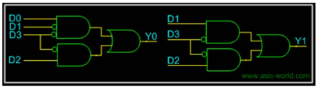
Now that we have the truth table, we can draw the Kmaps as shown below.
Kmaps

From the Kmap we can draw the circuit as shown below. For Y2, we connect directly to D3.

We can apply the same logic to get higher order priority encoders.
Tugas
Kumpulkan 1 pdf Materi tentang Decoder dan Enkoder beserta implementasi dalam dunia sistem komputer (wajib ada daftar pustaka)
Daftar Pustaka
1. Ronald J. Tocci, Neal S.Widmer, Gregory L. Moss, Digital Systems Principles and Applications TENTH EDITION, 2007, Pearson Education International
2. http://www.circuitstoday.com/ripple-carry-adder
3. http://www.asic-world.com/digital/combo2.html