Tujuan Pembelajaran/Kompetensi Akhir
1. Mahasiswa diharapkan dapat memahami Multiplexer
2. Mahasiswa diharapkan dapat memahami Demultiplexer
7.1 Multiplexer
A multiplexer (MUX) is a digital switch which connects data from one of n sources to the output. A number of select inputs determine which data source is connected to the output.
The block diagram of MUX with n data sources of b bits wide and s bits wide select line is shown in below figure.

MUX acts like a digitally controlled multi-position switch where the binary code applied to the select inputs controls the input source that will be switched on to the output as shown in the figure below.
At any given point of time only one input gets selected and is connected to output, based on the select input signal.
Mechanical Equivalent of a Multiplexer The operation of a multiplexer can be better explained using a mechanical switch as shown in the figure below.
This rotary switch can touch any of the inputs, which is connected to the output. As you can see at any given point of time only one input gets transferred to output.

7.1.1 2 to 1 MUX
A 2 to 1 line multiplexer is shown in figure below, each 2 input lines A to B is applied to one input of an AND gate. Selection lines S are decoded to select a particular AND gate. The truth table for the 2:1 mux is given in the table below.
Symbol

Truth Table

Design of a 2:1 Mux
To derive the gate level implementation of 2:1 mux we need to have truth table as shown in figure. And once we have the truth table, we can draw the K-map as shown in figure for all the cases when Y is equal to ‘1’.
Combining the two 1′ as shown in figure, we can drive the output y as shown below
Y = A.S’ + B.S
Truth Table

Kmap

Circuit

7.1.2 4 to 1 MUX
A 4 to 1 line multiplexer is shown in figure below, each of 4 input lines I0 to I3 is applied to one input of an AND gate. Selection lines S0 and S1 are decoded to select a particular AND gate. The truth table for the 4:1 mux is given in the table below.
Symbol

Truth Table

Circuit

7.2 Larger Multiplexers
Larger multiplexers can be constructed from smaller ones. An 8-to-1 multiplexer can be constructed from smaller multiplexers as shown below.
7.2.1 8-to-1 multiplexer from Smaller MUX
Truth Table

Circuit

7.2.2 16-to-1 multiplexer from 4:1 mux

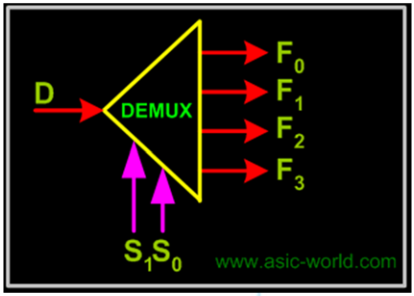
7.3 Demultiplexers
They are digital switches which connect data from one input source to one of n outputs. Usually implemented by using n-to-2n binary decoders where the decoder enable line is used for data input of the de-multiplexer.
The figure below shows a de-multiplexer block diagram which has got s-bits-wide select input, one b-bits-wide data input and n b-bits-wide outputs.

Mechanical Equivalent of a De-Multiplexer
The operation of a de-multiplexer can be better explained using a mechanical switch as shown in the figure below. This rotary switch can touch any of the outputs, which is connected to the input.
As you can see at any given point of time only one output gets connected to input.

1 to 4 Demultiplexer
1-bit 4-output de-multiplexer using a 2×4 binary decoder.

Example: 1-to-4 De-multiplexer
Symbol

Truth Table

Tugas
1. Kumpulkan Pdf tulisan (jurnal, artikel, materi) multiplexer dan demultiplexer.
2. Kumpulkan datasheet 1 IC multiplexer dan 1 IC demultiplexer.
Daftar Pustaka
1. Ronald J. Tocci, Neal S.Widmer, Gregory L. Moss, Digital Systems Principles and Applications TENTH EDITION, 2007, Pearson Education International
2. http://www.circuitstoday.com/ripple-carry-adder
3. http://www.asic-world.com/digital/combo2.html